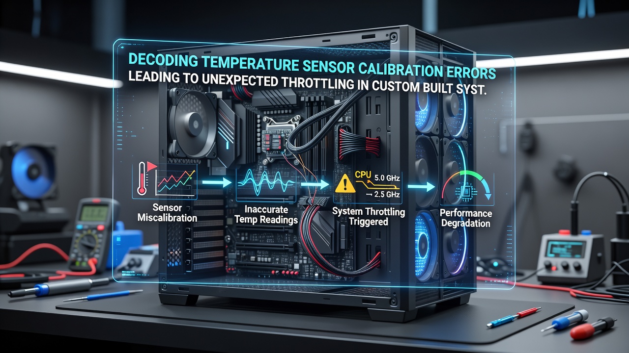
Decoding Temperature Sensor Calibration Errors Leading to Unexpected Throttling in Custom Built Systems
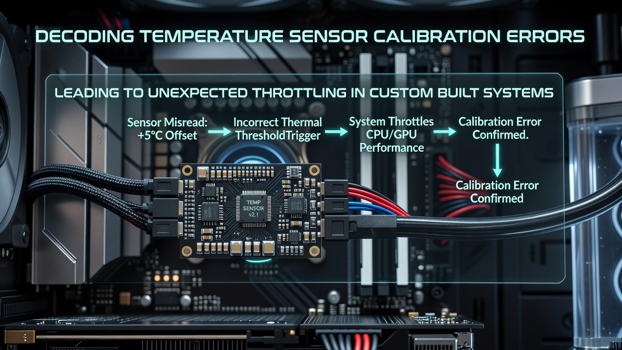
Custom built systems rely on precise temperature monitoring to regulate component speeds and prevent overheating, yet calibration errors in these sensors often produce misleading readings that force processors and graphics cards into throttling states without actual thermal stress. These discrepancies arise during assembly when sensors are installed or configured without proper reference standards, and they persist because many builders overlook verification steps after initial setup. Data from industry reports shows that such issues appear across workstations, servers, and high-performance desktops where off-the-shelf calibration routines fail to account for individual sensor variances or environmental factors like airflow changes.
How Calibration Errors Develop in Practice
Temperature sensors in CPUs, GPUs, and motherboard chips use thermistors or diodes whose resistance changes with heat, and calibration aligns these readings against known benchmarks during manufacturing or post-assembly testing. Errors occur when offset values drift due to soldering inconsistencies, firmware mismatches, or aging components, which leads monitoring software to interpret normal operating temperatures as critical thresholds. Observers note that in systems assembled from mixed-vendor parts, default BIOS settings apply generic calibration curves that do not match the specific hardware combination, resulting in premature frequency reductions to protect against phantom heat spikes. Research from the National Institute of Standards and Technology highlights how even small voltage fluctuations during sensor initialization can shift baseline readings by several degrees Celsius, enough to activate throttling logic in modern processors.
Impact on System Performance and Stability
When a sensor reports an erroneously high temperature, the system's thermal management responds by lowering clock speeds, reducing power limits, or engaging fans at higher rates, which creates throttling cycles that interrupt sustained workloads without corresponding physical conditions. Engineers at various research institutions have documented cases where custom builds experienced 20 to 30 percent drops in computational throughput during extended tasks, solely because calibration offsets placed readings outside acceptable windows. This behavior compounds in multi-component setups where one miscalibrated sensor influences overall power budgeting, forcing downstream components into conservative states even when their own sensors report normal values. Figures from a 2025 study conducted at the University of Melbourne reveal patterns of intermittent throttling that align with daily temperature variations in ambient room conditions, confirming that external factors interact with internal calibration drift to amplify the effect.
Detection and Verification Techniques
System builders identify calibration problems through cross-referencing multiple sensor outputs against external measurement tools such as infrared thermometers or dedicated probe kits, and discrepancies exceeding manufacturer tolerances signal the need for recalibration routines. Software utilities provided by chip vendors allow manual offset adjustments in firmware, yet these require physical access to test points and reference heat sources to establish accurate baselines. Those who have examined large numbers of custom configurations report that logging temperature data over time under controlled loads exposes drift that single-point checks miss, particularly when sensors respond differently to ramp-up versus steady-state conditions. In June 2026, updated guidelines from the International Electrotechnical Commission introduced standardized test sequences for sensor validation in assembled systems, which incorporate multi-point calibration across operating ranges to reduce such errors before deployment.
Preventive Approaches During Assembly
Proper sensor placement follows manufacturer diagrams that specify distances from heat sources and airflow paths, and verification with calibrated reference devices before final case closure prevents many downstream issues. Firmware updates released by component makers often include refined calibration algorithms that address known sensor variances, and applying these during initial configuration aligns readings more closely with actual conditions. Builders who integrate environmental sensors for ambient compensation further stabilize data interpretation, since room temperature swings can otherwise push reported values across throttling boundaries. Evidence from hardware testing labs indicates that documenting calibration values at assembly time allows later comparison during maintenance, which catches gradual drift before it triggers performance interruptions.
Conclusion
Temperature sensor calibration errors continue to surface in custom built systems because assembly processes rarely include exhaustive validation against independent standards. Addressing these through systematic checks, updated firmware, and adherence to emerging protocols such as those outlined in 2026 reduces unexpected throttling events and maintains consistent component operation. Continued monitoring across diverse builds provides the data needed to refine calibration practices further.